Driver’s rear brake

IMG_20160613_185317

Ready to assemble the driver’s side rear brake.  First the bolts go in from behind and the bearing retainer plate goes over them.

IMG_20160613_185132

Then the new wheel cylinder goes on the backing plate.

IMG_20160613_185531

The parking brake cable goes though the plate and the plate goes over the bolts.

IMG_20160613_185829

Then the grease seal goes on.  At this point anyone who actually knows how these go together is very upset with me because I just put the grease seal on backwards.  This should be interesting…

IMG_20160613_190114

The leak-catching grease cup thing is the last item in the stack.  Now that backwards grease seal is out of sight.  Meanwhile the plate and cap screws in my hand hold the parking brake cable to the back of the plate.

IMG_20160613_193249

The parking brake lever is attached to the trailing shoe and the cable is attached to the lever.  I had to file out the hole in the shoe a little to get the lever to fit.

IMG_20160613_193604

Trailing shoe installed

IMG_20160613_194703

Everything else installed.  Just to be sure I did it right I went back and looked at my pictures from the tear-down.  That is when I realized that grease seal is backwards.  Dammit.

IMG_20160613_204101

The trick here is to take apart as little as possible.  That turned out to be the self-adjusting rods and upper springs.

IMG_20160613_204155

There.  That is better.  As you can see I reused the gaskets on the seal.  They were not bad on this side but I ordered new ones for the other side.  Hopefully I can put the other side together without as much drama.  That is three wheels done!

Rear brake teardown

IMG_20160611_111154.

Time to go after the rear brakes.   I had to buy a 1 7/16 socket to get the axle nuts off.  After removing the axle nuts and wheels it was time to pull the hubs.

IMG_20160612_080144

At least I have the right tool for this job.  This puller is military surplus and was probably used to maintain jeeps back in the day.

IMG_20160612_080149

Notice how the axle nut is turned around on the end of the axle shaft.  This both protects the shaft from mushrooming and keeps the hub from flying into my face when it pops.

IMG_20160612_085649

After some serious hammering with a sledge the axle popped off.  Sounded like a rifle shot.  Once it came loose the hub came right off.

IMG_20160612_085642

For whatever reason the rear brakes are a lot less rusty and cruddy than the fronts.  This almost looks like it could work.  But it is getting torn down anyway.

IMG_20160612_092906

Backing plate and bearing retainer removed.IMG_20160612_092916

I bought new rear axle seals but they are the wrong ones.  That is the bad news.  The good news is the seals that are in there look just fine.  I cleaned up the axle taper to get that rust off.

IMG_20160612_101748

After a parts cleaning session things are looking decent.

IMG_20160612_111352

Parts that are not going to be painted.

IMG_20160612_111344

And parts that are.

IMG_20160612_111131

I  brush painted the visible parts of the hub.

IMG_20160612_111151

And sprayed the backing plate. Once all this dries it will be ready to put back together.


Brake lines and booster

IMG_20160606_182229

I got the driver’s side front brake line run.  It is the shortest brake line on the car and just hooks under the frame.  It would be tricky to cut and flare this line so I changed the routing a bit so I could use the length as-is.  I also crimped the stupid line a bit but I think it will be fine.

IMG_20160606_182235

Here is a fuzzy shot of the other end with the brake hose temporarily attached.

IMG_20160606_182756

I also pulled the power brake booster.  It is a rusty mess from leaking brake fluid.

IMG_20160606_182800

This boot on the pedal end of the booster is pretty far gone.  I will have to try and find one.

IMG_20160606_182749

Here is the pedal linkage. I should take this apart for cleaning, painting, and lubrication but at some point if I don’t stop taking the rusty bits off the whole car will be in pieces.  So I will just lube this up and leave it as is.

IMG_20160606_185238

I tested the booster as best I could by sucking on the vacuum port while holding the seal in place with a big socket.  It seems to not leak so it should be good.  I pulled the boot and grommet off and cleaned up the booster for painting.  The masking tape is to keep the paint out of the important bits.

IMG_20160606_190433

Painted the booster and hardware. This should be ready to install once I get the new master cylinder.  I need see about replacing that boot too.

Brake drum cleanup

VT_20160530_114630

I had to do spring maintenance on the Studebaker today so we did not get much done on the Jeep.  I went after the rust and crud with a wire brush in a drill motor.  I then cleaned it with a Brillo pad and water.  Then I dried the drum and sanded the surface.  This is what I ended up with.  Not great but tolerable.

VT_20160530_114647  VT_20160530_120007

I also cleaned up the threaded bits with taps and dies.  I just chased the threads in the hub, lug nuts, and wheel studs.  I have several new lug nuts and was tempted to just replace them but decided to just use what I have.

VT_20160530_073423

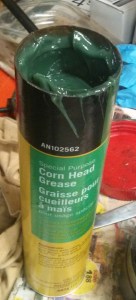
I also got three tubes of John Deere Cornhead Grease to use in the steering knuckles.  This is a very thin and slimy #0 grease that should be loose enough to lube the knuckle but thick enough not to run out.  I cleaned up my backup grease gun and put this stuff in it.

Locking hub cleanup

The passenger side of the car has the odd locking hub so I decided to clean up the set of used Warn M3B manual hubs from my parts pile.

VT_20160526_194713

This is the outer part of the hub where the locking knob is.  After washing the worst of the gunk off I started pulling out these locking pins.

VT_20160526_195521

With all the pins out this gear/ring thing unscrewed from the control knob.

  VT_20160526_194731

The body of the hub has two snap rings that appear to be holding it together.  I have no idea what I am doing here so this is where it gets a little scary.VT_20160526_194722

There is another inside snap ring on the back side as well as a spring holding something together on the outside. Rach removed the first snap ring and the innards slid out of the hub body.

VT_20160528_163005

And here are the innards.   The rollers are just sitting in there.

VT_20160528_163053

Rollers out.

VT_20160528_163523

Removing the outer spring from the other end allowed the removal of these nylon pads.  They go all the way round the hub.  It also allowed access to the inner snap ring.

VT_20160528_180943

Removing the inner snap ring just allowed the outer roller cage to rotate freely around the inner core.  We cleaned it up so we could see how it works better.

VT_20160528_180951

We can see how it works now.  Normally the hub sits with the rollers lined up with the 9 flats on the center of the hub.  When torque is applied to the center spline from the axle it turns the center forcing the rollers out against the outer body of the hub and the wheels turn.

VT_20160528_181002

This slot in the roller cage is longer than the others to trap the ends of that inner spring clip. This keeps the orientation of the cage to the hub the same all the time.  Not sure why that is important since I don’t see how it can move with the rollers in there anyway.

VT_20160528_180929

Cleaning parts.  The good news is the hub appears to be in great shape.

VT_20160528_181737

Rachel painted the outer body of the hub satin black.

VT_20160528_190810

We also cleaned up the knob end of the hub.  Rachael painted the letters and put red dots.  The control knob is bronze and the cap is some sort of aluminum alloy.   So we tried to be gentle with it.

Now it is time for some reassembly.  First of all let me apologize for the crappy pictures.  Turns out it is hard to take good pics in a dark garage when your hands are covered in wheel bearing grease.  I am not sure my phone will ever be the same.

VT_20160529_111726

First step is to put this inner snap ring back.  When I do the other hub I will leave this in place.  Taking it out did not get me much.  This was easy to put in except I lost my grip and launched it across the garage.  But I found it quickly.

VT_20160529_112346

Next these nylon pads go in.  They sort of snap into the holes around the end of the hub.

VT_20160529_112453

This spring goes around the outside and holds the nylon bits in.  Notice I am greasing the hell out of everything.

VT_20160529_112559

Next the cam pins go in.  I think there were nine of them.  I packed grease into the cage and coated the pins.  So this is where the pictures head downhill.

VT_20160529_113009

Pins are in.  They are just sitting there for now.

VT_20160529_113014

The hub housing serves as the outer “race” for the pins.

VT_20160529_113141

After coating the innards with yet more grease I put the inner hub assembly into the hub housing.

VT_20160529_113325

The whole thing is held together with a snap ring.

VT_20160529_113401

Next it is time to assemble the locking knob.  The top piece screws onto the center raised bit of the lower piece.

VT_20160529_113706

When the locking knob is turned to the lock position the inner piece “screws out” and engages the teeth on the top of the hub body.  This locks the hub together.

VT_20160529_114426

Moving the knob to the free position retracts the inner piece and unlocks the hub.  Here I have installed the 12 pins around the perimeter.  These keep the inner bit from turning and serve as “rails” for it to slide in and out on.

VT_20160529_115053

The two halves are held together by the bolts that tie the whole assembly to the wheel hub.  I reused the old gasket.  It is in pretty sorry shape but it just has to keep grease in and water out.  This guy is ready to go back on the car as soon as I finish cleaning up the brake drum.