Brake drum cleanup

VT_20160530_114630

I had to do spring maintenance on the Studebaker today so we did not get much done on the Jeep.  I went after the rust and crud with a wire brush in a drill motor.  I then cleaned it with a Brillo pad and water.  Then I dried the drum and sanded the surface.  This is what I ended up with.  Not great but tolerable.

VT_20160530_114647  VT_20160530_120007

I also cleaned up the threaded bits with taps and dies.  I just chased the threads in the hub, lug nuts, and wheel studs.  I have several new lug nuts and was tempted to just replace them but decided to just use what I have.

VT_20160530_073423

I also got three tubes of John Deere Cornhead Grease to use in the steering knuckles.  This is a very thin and slimy #0 grease that should be loose enough to lube the knuckle but thick enough not to run out.  I cleaned up my backup grease gun and put this stuff in it.

Locking hub cleanup

The passenger side of the car has the odd locking hub so I decided to clean up the set of used Warn M3B manual hubs from my parts pile.

VT_20160526_194713

This is the outer part of the hub where the locking knob is.  After washing the worst of the gunk off I started pulling out these locking pins.

VT_20160526_195521

With all the pins out this gear/ring thing unscrewed from the control knob.

  VT_20160526_194731

The body of the hub has two snap rings that appear to be holding it together.  I have no idea what I am doing here so this is where it gets a little scary.VT_20160526_194722

There is another inside snap ring on the back side as well as a spring holding something together on the outside. Rach removed the first snap ring and the innards slid out of the hub body.

VT_20160528_163005

And here are the innards.   The rollers are just sitting in there.

VT_20160528_163053

Rollers out.

VT_20160528_163523

Removing the outer spring from the other end allowed the removal of these nylon pads.  They go all the way round the hub.  It also allowed access to the inner snap ring.

VT_20160528_180943

Removing the inner snap ring just allowed the outer roller cage to rotate freely around the inner core.  We cleaned it up so we could see how it works better.

VT_20160528_180951

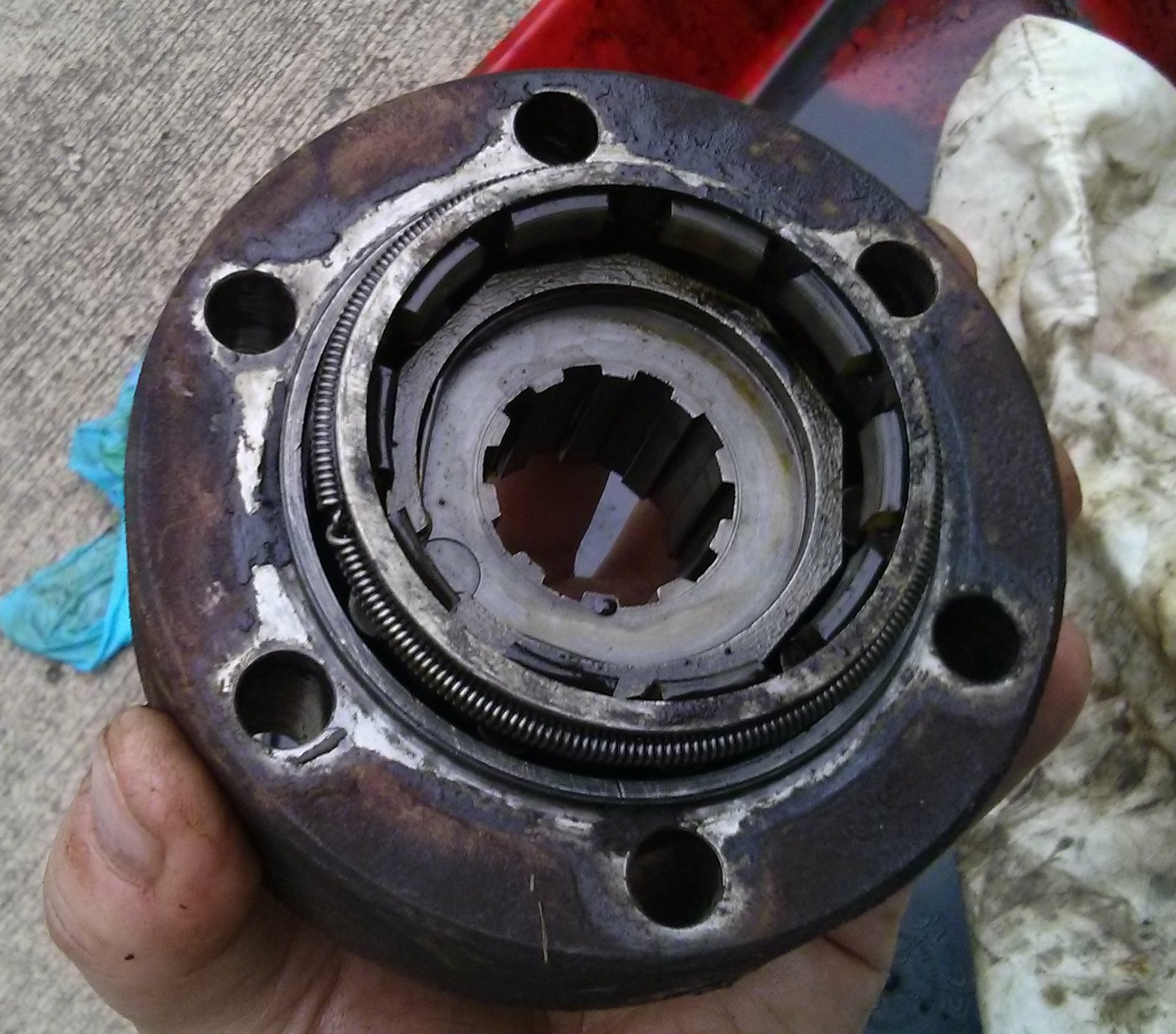
We can see how it works now.  Normally the hub sits with the rollers lined up with the 9 flats on the center of the hub.  When torque is applied to the center spline from the axle it turns the center forcing the rollers out against the outer body of the hub and the wheels turn.

VT_20160528_181002

This slot in the roller cage is longer than the others to trap the ends of that inner spring clip. This keeps the orientation of the cage to the hub the same all the time.  Not sure why that is important since I don’t see how it can move with the rollers in there anyway.

VT_20160528_180929

Cleaning parts.  The good news is the hub appears to be in great shape.

VT_20160528_181737

Rachel painted the outer body of the hub satin black.

VT_20160528_190810

We also cleaned up the knob end of the hub.  Rachael painted the letters and put red dots.  The control knob is bronze and the cap is some sort of aluminum alloy.   So we tried to be gentle with it.

Now it is time for some reassembly.  First of all let me apologize for the crappy pictures.  Turns out it is hard to take good pics in a dark garage when your hands are covered in wheel bearing grease.  I am not sure my phone will ever be the same.

VT_20160529_111726

First step is to put this inner snap ring back.  When I do the other hub I will leave this in place.  Taking it out did not get me much.  This was easy to put in except I lost my grip and launched it across the garage.  But I found it quickly.

VT_20160529_112346

Next these nylon pads go in.  They sort of snap into the holes around the end of the hub.

VT_20160529_112453

This spring goes around the outside and holds the nylon bits in.  Notice I am greasing the hell out of everything.

VT_20160529_112559

Next the cam pins go in.  I think there were nine of them.  I packed grease into the cage and coated the pins.  So this is where the pictures head downhill.

VT_20160529_113009

Pins are in.  They are just sitting there for now.

VT_20160529_113014

The hub housing serves as the outer “race” for the pins.

VT_20160529_113141

After coating the innards with yet more grease I put the inner hub assembly into the hub housing.

VT_20160529_113325

The whole thing is held together with a snap ring.

VT_20160529_113401

Next it is time to assemble the locking knob.  The top piece screws onto the center raised bit of the lower piece.

VT_20160529_113706

When the locking knob is turned to the lock position the inner piece “screws out” and engages the teeth on the top of the hub body.  This locks the hub together.

VT_20160529_114426

Moving the knob to the free position retracts the inner piece and unlocks the hub.  Here I have installed the 12 pins around the perimeter.  These keep the inner bit from turning and serve as “rails” for it to slide in and out on.

VT_20160529_115053

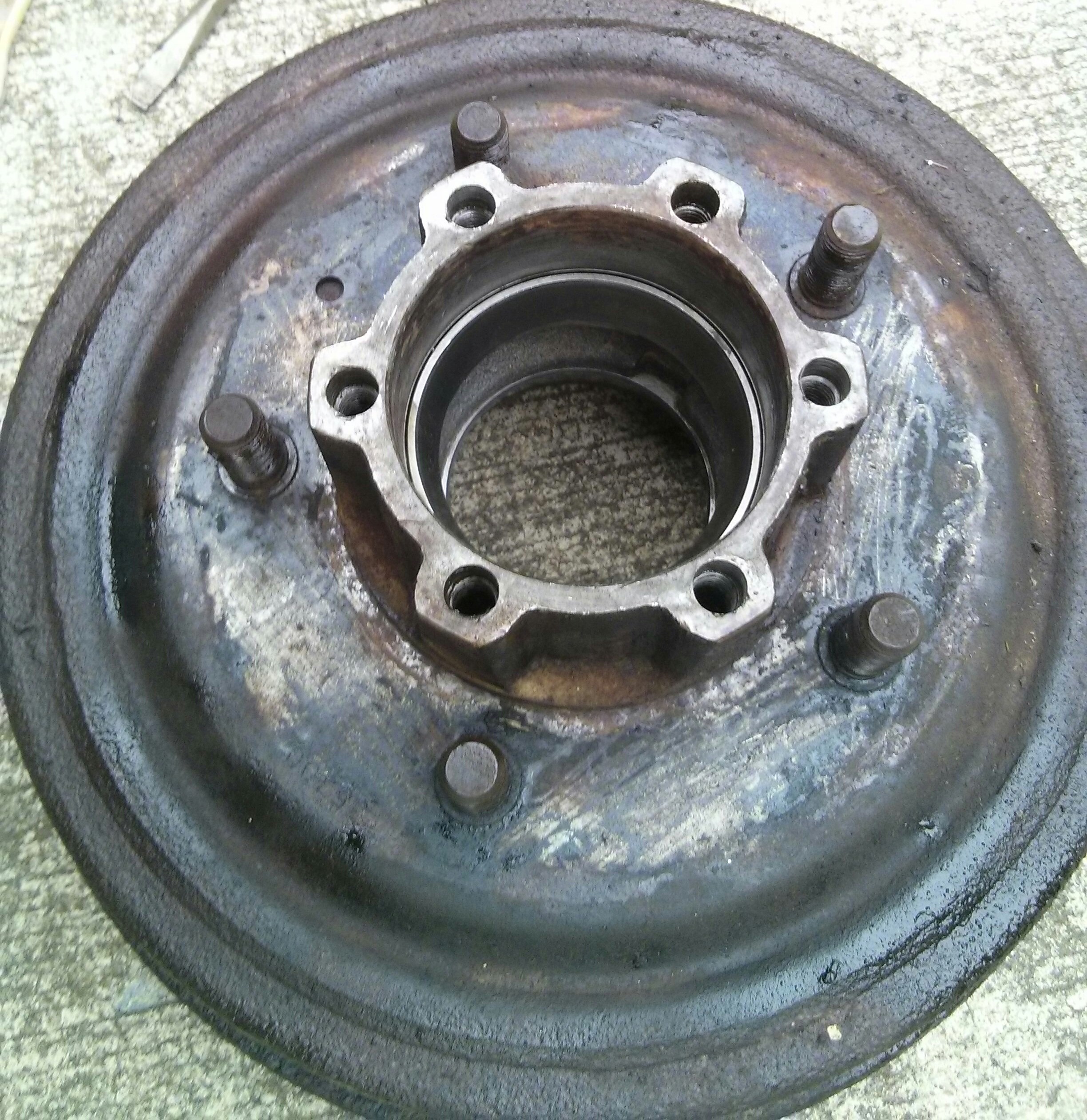
The two halves are held together by the bolts that tie the whole assembly to the wheel hub.  I reused the old gasket.  It is in pretty sorry shape but it just has to keep grease in and water out.  This guy is ready to go back on the car as soon as I finish cleaning up the brake drum.

Passenger side axle back together

VT_20160526_180324

Getting the knuckle seal on I spend a bit of time trying to get the rubber grease seal (red arrow) to snap into the knuckle before I realized I was making it too hard.  I started putting the retainer on and used that to force the seal into place.  Before I started I squirted oil on the felt seal (blue arrow) where it rubs on the ball.  Not sure if that is necessary but it felt right.

VT_20160526_181909

Looks good.  The bolts are snug but not stupid tight.

VT_20160526_194430

Next Rachael put the axle in while I put some sealer on the spindle.  It took all of our hands to get the parts held in place while putting the bolts through so I did not get any pictures.  Rachael torqued the bolts to 30 ft-lbs.  I just guessed at that torque.

VT_20160526_194443

Next the “s” shaped little brake line and the new brake hose.  We reused the old clip.

VT_20160526_194434

Brake hose is attached.  Three more wheels to go!

VT_20160526_194556

While Rachael worked on the knuckle I was cleaning parts.  Bearings look good.

VT_20160526_194544    VT_20160526_194533

Got the drum and hub de-greased too.  The drum does not look worn at all.  It was probably turned “recently”


Building the brakes back up

IMG_20160525_193753

I only had a little time tonight so I decided to put the brakes back together.  To help me do this later on the other 3 I will cover every step.  Here we have to backing plate ready to rock.

IMG_20160525_194243

The first step is bolting the wheel cylinder on.  For some bizarre reason the car uses 4 unique wheel cylinders.  Crazy.  This is the one for the passenger side front.

IMG_20160525_194640

Done.

IMG_20160525_194923

Next these rods go in. I lubricated both ends of the rods.

IMG_20160525_195104

Brake shoes go into the slots on the rods.

IMG_20160525_195847

Next the retainer rod and spring go for the left (rear) shoe.

IMG_20160525_195217

Next the ratcheting spring for the self-adjuster goes over the end of the rear shoe.

IMG_20160525_195856

Here is the adjuster cleaned and lubricated.  Hard to believe this cleaned up so well.

IMG_20160525_200121

Self adjuster is in place on the ends of the shoes.

IMG_20160525_200126

Then the other shoe’s retainer goes on.

IMG_20160525_200549

The first of my new springs goes on next.  This holds the self-adjuster together.

IMG_20160525_201123

Then a new spring on the leading (front) shoes.  These springs were $8 each but it is amazing how much stronger the new springs are than the old ones I took off.

IMG_20160525_201655

Then the spring on the trailing shoe.  Notice how they go next to each other.

IMG_20160525_201853

Next the linkage for the self adjuster goes in.  The pivot point screws into the trailing shoe.

IMG_20160525_201921

Done.  Looks purdy!

Passenger side front brake

IMG_20160514_155435

I decided to do one wheel at a time on the brakes.  Since the backing plate, hoses, and everything else are a rusty mess  I decided to just remove everything.  There are 6 bolts on 3 lock plates that hold everything together.   Once I bent the tabs on the lock plates back I hit the bolts with an impact wrench.

IMG_20160514_161959

With the backing plate and brakes out of the way I next removed the hose.   The lower end is held on by two of the kingpin bolts.  Impact wrench time again!

IMG_20160514_162837

I had already removed the brake line from the upper end of the hose.  So all I had to do to get the hose out was remove this rusty-ass clip.  This is in pretty bad shape but might be salvageable.

IMG_20160514_162329

After cleaning around it to try and keep dirt out of the axle I popped the spindle off.  Here is the spindle and hardware.  The spindle looks to be in good shape and the bushing inside it does not seem badly worn.

IMG_20160514_165306

With the backing plate on the workbench this is the easiest brake job ever.  I carefully photographed each step as I took the brakes apart.  I am going to replace the cylinders and springs.  Hopefully the rest can be saved.

IMG_20160514_175327

Good thing I have new wheel cylinders.  This is pretty gross.  I could not get the piston to move at all.  I will try and get these apart later but for now they go in the discard pile.  Time for a massive parts-cleaning party.

IMG_20160514_190852

I got everything painted but the backing plate.  That will have to wait until next time though.  It is too cold to keep painting tonight.

IMG_20160514_192348

I also hit the frame where the brake hardware attaches with a wire brush.  When it gets a little warmer I will paint all this too.  But time to knock off for today.